The UL1558 low-voltage switchgear complies with the IEEE C37.20.1 standard and features a standard four-compartment design arranged vertically from top to bottom, with each compartment 21 inches in height, accommodating various circuit breaker specifications. The main busbar position is flexible and can be arranged at the top, middle, or bottom.
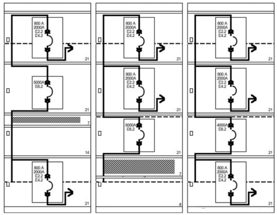 The control circuit unit is installed nearby the circuit breaker and includes auxiliary switches for closing and opening, trolley position auxiliary switches, and secondary connections. A standard structure provides a metal panel above each circuit breaker compartment, used for mounting various control circuit devices. Fuses for the closing and tripping circuits are mounted in snap-in fuse holders on the front. Indicators, meters, and similar equipment are generally not installed on the door panels of the circuit breaker compartments.
Up to three indicator lamps can be mounted on the panel, and the lamps can be replaced from the front. A toggle switch for testing the closing and tripping circuits of the circuit breaker may also be installed on the panel. The panel is removable to provide access to the terminal block. A switch to reduce permissible current and arc energy may also be mounted on the panel, enabling convenient maintenance operations on the circuit breaker‘s outgoing circuit. The panel also provides an engraved circuit nameplate for the circuit breaker.
Accessibility of fuses: If the removable component consists of a fuse-equipped circuit breaker, the fuse shall only be accessible when the removable component is withdrawn to the test, disconnected, or withdrawn position.
The compartment can accommodate equipment such as voltage transformers, metering devices, control power transformers, and monitoring equipment. Voltage transformers and control power transformers are installed within the auxiliary compartment and are protected by primary pull-out current-limiting fuses and secondary fuses. Current transformers are typically mounted on the main isolation studs of the compartment for easy access.
Interchangeability of removable units: All removable units of the same type and rating within a given assembly shall be physically interchangeable in their respective fixed enclosures. This does not require electrical interchangeability of secondary control circuits. Measures shall be taken to prevent removable units with higher continuous current ratings from being inserted into circuit breaker compartments rated for lower continuous current values. Similarly, measures shall be taken to prevent removable units with lower short-circuit current ratings from being inserted into circuit breaker compartments rated for higher short-circuit current values.
The fuse is located on a separate removable element, and the current-limiting fuse may be installed on this separate removable component. The requirements of 7.11.4 apply to these components; additionally, they must only be used in series with a circuit breaker. Fuses on these removable elements shall be interlocked so that they must be disconnected from the main circuit before access. Interlocking between the circuit breaker and its associated fuse shall be provided to prevent connection or disconnection under load.
The control wiring connection between the fixed structure of the secondary disconnection device and the detachable component shall be equipped with automatic (self-mating) contacts or manual plug-and-socket connectors for disconnecting. Manual control connectors shall be interlocked or inaccessible to prevent connecting or disconnecting the control circuit when the detachable component is in the connected position; additionally, the detachable component should not be able to be installed in the connected position unless the manual control connector is connected. By means of a manual arrangement, all connections shall be capable of being simultaneously grouped and connected to the main contacts on the detachable component and the mating socket on the fixed structure.
The total area of the cable connection space, independent of all protrusions, obstructions, or moving parts, shall not be less than 250% of the total cross-sectional area of the maximum number of cables that may be used in that space.
Up to three indicator lamps can be mounted on the panel, and the lamps can be replaced from the front. A toggle switch for testing the closing and tripping circuits of the circuit breaker may also be installed on the panel. The panel is removable to provide access to the terminal block. A switch to reduce permissible current and arc energy may also be mounted on the panel, enabling convenient maintenance operations on the circuit breaker‘s outgoing circuit. The panel also provides an engraved circuit nameplate for the circuit breaker.
Accessibility of fuses: If the removable component consists of a fuse-equipped circuit breaker, the fuse shall only be accessible when the removable component is withdrawn to the test, disconnected, or withdrawn position.
The compartment can accommodate equipment such as voltage transformers, metering devices, control power transformers, and monitoring equipment. Voltage transformers and control power transformers are installed within the auxiliary compartment and are protected by primary pull-out current-limiting fuses and secondary fuses. Current transformers are typically mounted on the main isolation studs of the compartment for easy access.
Interchangeability of removable units: All removable units of the same type and rating within a given assembly shall be physically interchangeable in their respective fixed enclosures. This does not require electrical interchangeability of secondary control circuits. Measures shall be taken to prevent removable units with higher continuous current ratings from being inserted into circuit breaker compartments rated for lower continuous current values. Similarly, measures shall be taken to prevent removable units with lower short-circuit current ratings from being inserted into circuit breaker compartments rated for higher short-circuit current values.
The fuse is located on a separate removable element, and the current-limiting fuse may be installed on this separate removable component. The requirements of 7.11.4 apply to these components; additionally, they must only be used in series with a circuit breaker. Fuses on these removable elements shall be interlocked so that they must be disconnected from the main circuit before access. Interlocking between the circuit breaker and its associated fuse shall be provided to prevent connection or disconnection under load.
The control wiring connection between the fixed structure of the secondary disconnection device and the detachable component shall be equipped with automatic (self-mating) contacts or manual plug-and-socket connectors for disconnecting. Manual control connectors shall be interlocked or inaccessible to prevent connecting or disconnecting the control circuit when the detachable component is in the connected position; additionally, the detachable component should not be able to be installed in the connected position unless the manual control connector is connected. By means of a manual arrangement, all connections shall be capable of being simultaneously grouped and connected to the main contacts on the detachable component and the mating socket on the fixed structure.
The total area of the cable connection space, independent of all protrusions, obstructions, or moving parts, shall not be less than 250% of the total cross-sectional area of the maximum number of cables that may be used in that space.